NEMA Wiring Diagram Guide for Electrical Specialists
About seventy percent of electrical breakdowns within establishments result from poor wiring practices. Such data emphasizes the requirement of complying with established protocols, underscoring NEMA wiring diagrams’ importance for electrical experts. Via these drawings, wiring arrangements that meet both operational efficiency and supreme protection norms are presented.
The objective of this document is to arm electrical practitioners with profound understanding into NEMA norms. Highlighting the significance of correct electrical arrangements is vital. Through mastering these guidelines, specialists can drastically reduce the likelihood of incidents and ensure they comply with safety protocols supported by Installation Parts Supply. Knowledge in l 14-30 plug is vital whether developing modern setups or servicing existing ones, as it improves the ability to offer safe and consistent electrical systems.
Key Conclusions
- NEMA wiring diagrams are crucial for maintaining electrical safety and conformity.
- Proper wiring techniques can minimize electrical issues considerably.
- Understanding NEMA norms enhances the effectiveness of electrical installations.
- Installation Parts Supply encourages following regulatory standards in electrical operations.
- NEMA schematics cover a broad spectrum of applications across multiple sectors.
Understanding NEMA Norms and Why They Matter
NEMA norms are essential in the electrical field, steering safety and functionality meticulously. Formulated by the National Electrical Manufacturers Association, they define pivotal criteria for creating, examining, and identifying electrical gear. This ensures uniformity and reliability across all electrical configurations, which is invaluable.
What Are NEMA Criteria?
NEMA categories differ from grades 1 up to 13. Every level delineates the parameters necessary for electrical apparatus to operate optimally. For instance, NEMA 1 provides basic indoor security but does not offer dust shielding. On the other hand, NEMA 4 ensures devices is watertight, a necessity for surviving substantial water immersion. Grasping these designations is crucial in choosing appropriate devices.
Why NEMA Criteria Are Important for Electrical Protection
The function of NEMA criteria in ensuring electrical safety is profound. They play a significant part in reducing electric shock, device malfunctions, and fire hazards. Correct adherence to NEMA classifications allows devices to function securely under certain ambient conditions. For external application, NEMA 3 classifications offer protection against the weather, safeguarding the apparatus from inclement weather like precipitation and snow. In areas at risk of explosions, classifications such as NEMA 7, 8, and 9 are essential for ensuring safety.
Implementations of NEMA Norms in Wiring Schematics
The implementation of NEMA standards in wiring drawings is vital for protected, optimal electrical systems. These diagrams make use of uniform symbols and layouts based on NEMA ratings, facilitating the comprehension of intricate electrical configurations. Such standardization is advantageous. It promotes clarity, standardization, and diminishes confusions, thus improving electrical security across home and industrial landscapes.
NEMA Wiring Diagram Fundamentals
NEMA wiring schematics are crucial for electrical specialists, ensuring complicated junctions unambiguous. They detail the linkages and components in various installations. By understanding the elements, categories, and notations of NEMA schematics, technicians can boost their operations in installations and upkeep.
Elements of NEMA Wiring Schematics
NEMA schematics comprise crucial parts for particular electrical configurations. You’ll see wiring terminals, connectors, and various equipment for secure junctions. Every piece ensures energy is distributed efficiently, following safety guidelines.
Varieties of NEMA Wiring Diagrams
NEMA uses different schematics, like connection schematics and electrical arrangements. Schematics detail appliance associations, while layouts display power flow. Selecting the correct drawing facilitates problem solving and deployment.
Frequent Notations Found in NEMA Wiring Drawings
Symbols in wiring schematics are vital for clear clarity. They depict switches, circuits, and interfaces. Recognizing these symbols assists groups read schematics properly. Thus, it guarantees configurations adhere to NEMA norms.
NEMA Wiring Schematic Characteristics
For electrical experts, understanding the core components of detailed electrical wiring drawings is crucial. These diagrams bring both lucidity and completeness, matching setups with NEMA standards. They demand accurate labeling and proportioning to minimize deployment issues. This encourages a more secure and more efficient workplace.
Key Attributes of Correct Electrical Wiring Schematics
Precise electrical wiring diagrams are essential in electrical initiatives. They embody important features such as:
- Lucidity: Schematics are required to be unambiguous, reducing errors in understanding.
- Completeness: They should incorporate all essential components, linkages, and electrical standards.
- Standard Compliance: Adherence to NEMA standards is imperative for securing safety and functionality.
- Detailed Labeling: Distinct markings on each part are essential for understanding and minimizing errors.
- Correct Scaling: The dimensions should replicate the actual setup to represent the arrangement correctly.
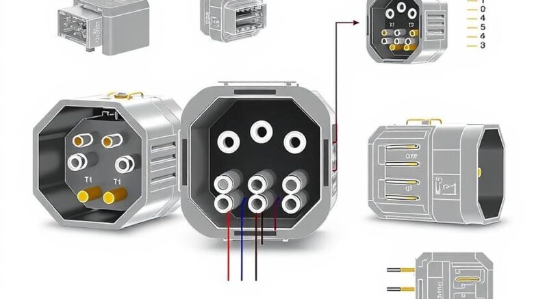
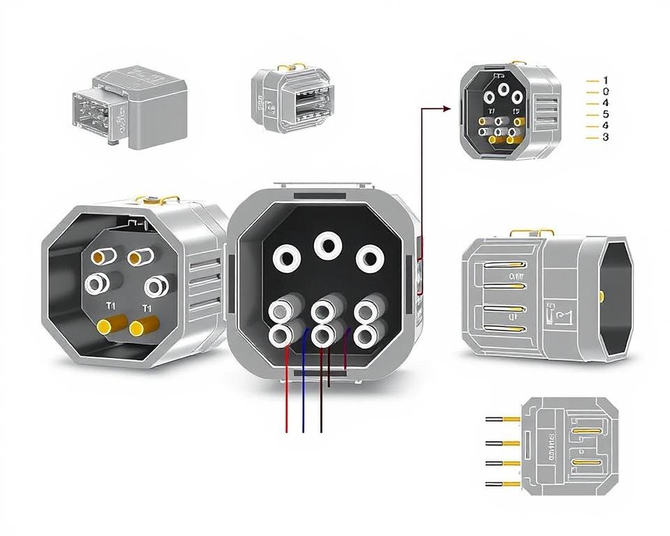
Comprehending NEMA Connector Layout
The insight into NEMA connector layout is vital for making accurate connections in electrical networks. Understanding of specific pin arrangements upholds safety and device performance. There are a variety of NEMA couplers, crafted for different voltages and amperages, encompassing:
| NEMA Connector Type | Current Rating | Voltage Level |
|---|---|---|
| L5-15 | 15A | 125V |
| L5-20 | 20A | 125V |
| L14-20 | 20A | 125/250V |
| L1430C | 30A | 125/250V |
| L620C | 20A | 250V |
| L1430C | 30A | 125/250V |
| L630R | 30A | 250V |
Comprehending NEMA connector pinouts is vital for stable junctions, enhancing performance. It’s critical to match interfaces with appliances accurately using twist-lock or straight blade variants, to avoid dangers.
NEMA Appliance Wiring
NEMA device wiring encompasses diverse arrangements for protected electrical appliance connections. These standards guarantee that appliances operate in unison reliably, reducing danger. Grasping the various NEMA appliances and their wiring is crucial for electricians.
Multiple Categories of NEMA Units
NEMA categorizes units by kind based on power levels and flow demands. Essential arrangements are:
- 2-Pole, 2-Wire
- 2-Pole 3-Wire Grounding
- 3-Pole 3-Wire
- 3-Pole 4-Wire Grounding
- 4-Pole, 4-Wire
- 4-Pole 5-Wire Grounding
These arrangements are utilized in homes and factories, supporting 125V, 208V, and 480V.
NEMA Plug Wiring Explained
NEMA plug wiring differs to suit diverse power needs, with rotary-lock types ensuring consistent junctions in unstable environments. Such as, the L5-15 plug operates at 15 amperes, frequently used in commercial locations, whereas the L14-20 is designed for 20 amperes at 125/250 volts.
The NEMA designation system assists in picking the appropriate plugs, emphasizing attributes like polarity and earthing. This meticulousness guarantees that equipment perform reliably.
NEMA Receptacle Wiring Instructions
Accurate wiring of NEMA receptacles aligns with electrical codes and safety guidelines. For example, L530R receptacles are rated for 30 A at 125 V, with L630R variants for 250 volts. Adequate grounding is essential to avoid electrical accidents.
Choosing approved NEMA plugs and outlets ensures secure, regulation-compliant installations. It’s vital to consult authoritative guidelines when implementing.
NEMA Motor Wiring and Implementations
NEMA motor wiring is crucial in electrical design, notably for industrial use. Understanding how NEMA motor setup works ensures that machines are installed for best efficiency. These motors, like single-phase and tri-phase types, need correct wiring to function reliably and optimally.
Overview of NEMA Motor Wiring
Comprehending NEMA motor wiring necessitates understanding of connections and setups. Most three-phase motors offer dual-voltage, signifying they can work on both low (208-230V) and high voltage levels (460V). High voltage wiring makes a motor use less current than at low voltage. High voltage perks comprise smaller wires for the supply, a significant benefit for units above 10 HP.
While both NEMA and IEC devices are employed in the industry, NEMA models are generally larger and more expensive than IEC ones for under 100 HP deployments. NEMA starters range from size 00 to 9, fit for diverse applications. A standard feature in NEMA controllers is a Trip Rating of 20, intended to trigger when a motor’s amperage exceeds six times the Full Load Amperage in 10 s.
Opting for the Right NEMA Motor Setup
Choosing the correct NEMA motor arrangement affects overall operation and security. A standard three-wire control circuit utilizes three wires for a on/off pushbutton panel, allowing simple motor control. Common three-phase configurations include the 12 Lead Dual Voltage and 6 Lead, facilitating Wye and Delta arrangements.
IEC motor starters commonly feature phase loss detection, increasing safety. They also offer adjustable Trip Ratings for customized protection in low voltage operations. Additionally, many models have temperature safeguards, vital for single-phase and Dual Voltage systems.
| Arrangement | Voltage Level | Current Rating | Typical Use |
|---|---|---|---|
| 12 Lead Dual Voltage | Dual Voltage (208-230V / 460V) | Varies by motor size | Wye Start and Delta Run setups |
| 6 Lead | One or Dual Voltage | Maximum 32A | Both Wye and Delta arrangements |
| Single Phase | One Voltage | Varies (1-5 amps adjustment) | Applications with Two Speed, Two Winding |
| Delta Connection | High Voltage | Variable | Various applications including Current Transformers |
As a Final Point
Comprehending NEMA wiring schematics and criteria is essential for electrical experts seeking to improve their capabilities and comply with electrical safety standards. These guidelines secure secure and high-performing electrical setups but also avert hazards stemming from incorrect wiring. As mentioned, complying with NEMA standards leads to the augmented functionality of various NEMA appliances and setups.
For electrical professionals, the availability of superior resources can significantly impact the result of their tasks. Installation Parts Supply offers a vast range of wiring supplies aligned with NEMA standards. This allows professionals to get vital components for fulfilling these important requirements. High-quality supplies and comprehensive understanding of NEMA wiring drawings substantially improve project safety and effectiveness.
In your journey through electrical deployments, always put safety and precision above all. Mastering NEMA criteria delivers the understanding needed for executing optimal procedures accurately. This guarantees that each electrical connection established aligns with high-quality standards.
FAQ
Identify NEMA wiring drawings?
NEMA wiring drawings illustrate the arrangements and linkages of NEMA-standard electrical appliances. They adhere to safety and operational standards set by the National Electrical Manufacturers Association.
Why are NEMA standards important for electrical security?
NEMA norms are essential to defining safety and functional benchmarks for electrical equipment. These standards enable electrical professionals minimize electric shock, equipment failure, and burn dangers.
Identify the key parts are crucial in a NEMA wiring schematic?
Key elements in a NEMA wiring drawing include circuit configurations and connection schematics. These diagrams also feature detailed markings and show the electrical system’s various parts correctly for setups.
Identify the varieties of NEMA wiring diagrams are available?
Multiple NEMA wiring schematics cater to various applications, including energy distribution layouts and interconnection diagrams for components. Each layout serves a distinct role in electrical installations.
What are common symbols used in NEMA wiring diagrams?
Standard symbols in these diagrams symbolize toggles, interruptors, sockets, and additional components. Use of these symbols encourages effective communication and precise interpretation of wiring diagrams.
Which are the key characteristics of accurate electrical wiring schematics?
Correctness in electrical wiring drawings is characterized by their clarity, comprehensiveness, and clear annotation. They should conform to NEMA standards to prevent faults in setup.
Explain a NEMA connector pinout?
A NEMA connector pinout outlines electrical connections at a connector, showing specific pin functions. This secures safe and optimal connections in electrical systems.
What are the different types of NEMA units?
NEMA units consist of various electrical receptacles and couplers, like connectors and outlets. They are engineered for various current and voltage levels criteria to meet unique application requirements.
How is NEMA plug wiring arranged?
NEMA plug wiring depends on specific current and power needs, following security protocols and electrical codes for various electrical applications.
Identify the recommendations are there for NEMA outlet wiring?
Recommendations for connecting NEMA receptacles underline following electrical codes, guaranteeing correct polarity, and selecting appropriate wire sizes. This ensures both protection and operation in electrical configurations.
How can I wire a NEMA motor properly?
To connect a NEMA motor, one must comprehend its particular single-phase or tri-phase configuration. Choosing the appropriate wiring technique is crucial, in addition to observing electrical protection for enhanced motor functionality.
Which factors should be considered when opting for a NEMA motor configuration?
Choosing a NEMA motor arrangement necessitates an analysis of the application’s voltage and current demands and operational characteristics. It’s also crucial to verify alignment with pre-existing equipment for guaranteed performance and protection.